CONTROL OF ELECTRIC HEATING RESISTANCES IN THE INDUSTRY
There is a widespread demand for “supplying heat” in the industrial processes: the wide diffusion and application of the thermoregulators in the machines and in the industrial plants is a fair evidence.
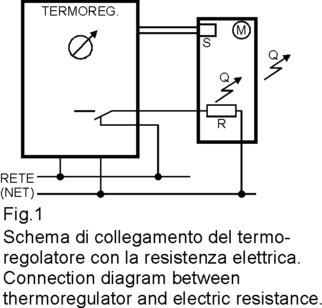
Along with each thermoregulator there is always at least one electric resistance connected as showed in Fig. 1.
When it is requested to heat a mass M up to the temperature T1, necessary to develop a required working of the machine (for instance the melting of plastic, rubber, for polyethylene gluing etc.), the temperature value T1 is set on the thermoregulator, and the temperature of the mass M is detected by a probe; if the detected value is lower than the set value, the termoregulator connects to the mains the resistance R (directly or through an external contactor); the resistance will supply heat Q to the mass M.
Afterwards the temperature will increase, until the value detected by the probe becomes equal to the set value; at this moment the thermoregulator disconnects the resistance.
In steady condition the resistance will transfer to the mass M as much heat as it is the heat that the mass loses around; in this way, on average, the mass temperature is constant and equal to the value set by the thermoregulator.
Often the thermoregulator is equipped with suitable controls, so if the probe has anomalies, they are pointed out so that the operator can take action to resolve them.
Another important component of the system is the resistance R. If it is interrupted, the temperature T1 could not be reached or kept. The thermoregulator is not able to detect if the resistance is interrupted: the probe indicates that T< T1 and consequently the thermoregulator connects the resistance R. In absence of heat, the temperature T is lower than T1, the operator sees that the thermoregulator is connected, and he may realize too late that the resistance R is interrupted. It is therefore necessary to point out immediately the resistance interruption, so that the operator takes actions accordingly, and stops the industrial process going on in presence of a decreasing T1 along with the production damages. In the practical applications the technical picture is much more complex than what has been schematized above. The thermoregulator may not be present, or there might be more that one; in many cases the resistance is “a group” of resistances of variable number and connected according to suitable schemes according to the available voltages and the type of resistance.
Basing on the manufacture principle of the heating resistances, it immediately appears that the most frequent failure in the resistances is the interruption.
In theory it is possible, although not very frequently, the short circuit of the two terminals; in this case the mains must be protected by means of fuses or automatic switches; in any case the final result is again an interruption of the current flow.
Another possible inconvenience is the insulation failure: the degradation of the insulating material placed between the voltage wire and the external surface of the resistance causes a “current leak” from the wire to the resistance surface, which is often connected by metal to the machine mass; the result is that the machine “goes into voltage” and the operator who gets in touch with this machine can be subject to electrocution. The insulation failure does not compromise the temperature value T1, but it is dangerous for the operator (it can be detected with a differential relay).
The above explanations have pointed out that the not correct working of the resistance can be detected by monitoring the electric current of the resistances themselves.
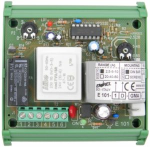
| Model | Connection | CompensatedSet Point | I=0 ALARM | Built-inCT | Number of Ranges | Case |
| E 101 | 1 Resistance | NO | YES | YES | 6 | E 101-S (mounting by screws connection: 88x72x50 mm)E 101-D (for DIN rail open frame: 90×92,5×70 mm) |
| E 073 | 3 Groups of resistances | YES | NO | YES | 2 | For DIN rail, open frame: 180x97x55 mm |
The resistances can be supplied by single-phase voltage or three-phase voltage.
In the table the first device is supplied by the single-phase voltage and the resistance can be SINGLE or a GROUP OF RESISTANCES (2 or more resistances).
The fourth device in the table is for n° 3 GROUPS of resistances which have star connection or delta connection, supplied by a three-phase mains. If the application requires a resistance per phase, an A3-06 (phase failure relay) can be used.
ELECTRICAL RESISTANCES CONTROL FAMILY : 1 RESISTANCE / 1 GROUP OF RESISTANCES / 3 GROUPS OF RESISTANCES TAB-PDF VERSION
|
Model |
Connection | Compensated Set Point |
I=0 ALARM |
Built-in CT |
Number of Ranges |
Case | Field / Application |
Datasheet |
| E 101 | 1 Resistance | NO | YES | YES | 6 | E 101-S (Mount. by Screw Connection: 88x72x50 mm) E 101-D (Open Frame DIN Rail: 90×92,5×70 mm) |
Electric Heating Ovens |
E101 |