The three-phase voltage is generated in the power plants and distributed on the territory by a national Electricity Company. The operator has not chance to modify it. While the current depends on the load applied and therefore it depends on the operator, the voltage depends on the Electricity Company. Nevertheless the industries require to keep under control the incoming three-phase mains or the mains which supplies a motor.
1 SET POINT MAX + 1 SET POINT MIN
During the distribution of the mains, the voltage drops caused by the electric current flowing through the cables are necessarily present; an operator who is supplied by a “tail” of the “mains” will receive a voltage affected by variations depending on the absorptions of the other operators.
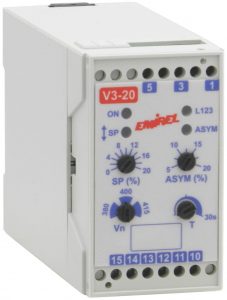
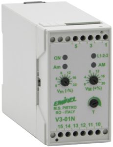
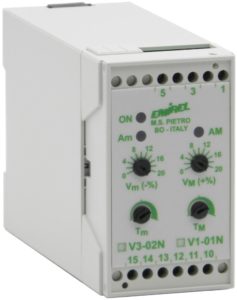
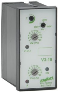
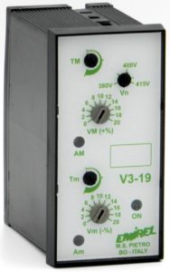
Therefore it may happen that the operator receives a too low voltage or a too high voltage: to avoid these 2 possibilities, the operator can use a relay with 2 set points: one of max and one of min, such as V3-01N,
V3-02N, V3 -12, V3-18, V3-19, V1-11.
Too high voltage solicits the insulation of the equipment, a voltage drop causes increases of the currents in the motors and when the voltage is too low the motors stop for “torque” failure.
L1, L2, L3 (PHASES SEQUENCE)
Another characteristic of the three-phase voltage is the sequence of the 3 phases L1, L2, L3.
The three-phase motors rotate in one direction or another depending on the “direction” in which the three phases are connected to the motor terminals.
In some applications, the motor must rotate in the direction indicated by the designer and not in the opposite direction, therefore it is necessary to control the direction of rotation to prevent that a hasty maintenance inverts 2 phases and causes serious damages to the machine.
There are voltage relays which recognise the phases sequence and which must be connected in parallel to the motor terminals.
These relays are also used to recognise the failure of one phase.
PHASE FAILURE
In the three-phase voltage one phase may fail, that is one of the 3 wires is interrupted (faulty fuse, insulated contact of remote control switch, loose terminal, etc.), this occurrence is very damaging for the three-phase motors: in fact, when the motor receives 3 three-phase currents, inside it a rotating magnetic field which drags the ROTOR is created and the motor distributes power.
When one of the three wires is missing, the motor is supplied by only two wires, that is in SINGLE PHASE, 2 rotating magnetic fields are created in the opposite direction and the motor struggles to start, or, if it is already in motion, it tends to stop because it does not have power.
When there is a phase failure, the motor always overheats, so the motor is deteriorated irreparably.
The recognition of the phase failure situation based on the voltmetric principle (amplitude and phase of the voltages) is complicated by the presence of the back voltage generated by the motor on the terminal 2 no longer connected to the phase (See Figures below).
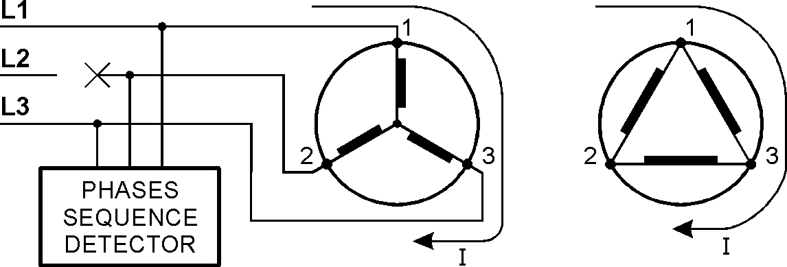
When the terminal 2 of the motor is connected to L2, the DETECTOR of phases sequence detects the 3 voltages at 400V displaced of 120° and runs correctly.
When the terminal 2 is no longer connected to L2, it becomes the site of a voltage generated inside the motor by a sort of divider of windings which are run by the distorted single-phase current.
Since the terminal 2 remains connected to the phases sequence detector, it can run not correctly if the back voltage is too high.
Unfortunately the value of amplitude and the phase of the back voltage are not easily predictable because they depend on various factors:
– Value of the single-phase I
– Single-phase I distortion
– Does the motor rotate or stop?
– Does the three-phase mains, which supplies the motor, supply other loads as well?
– Is the single-phase I a large or small part of the three-phase generator current?
A phases sequence detector that must recognise the phase failure, with the voltmetric method, fixes the value that the recovery voltage must have, so that the phase failure is recognised: for example 80% of Vn, 70% of Vn (Vn is the nominal value of the mains voltage).
Unfortunately no one is able to affirm if a certain application will have a back voltage greater than or less than 80% of Vn or 70% of Vn.
The phase failure can be recognised with the Amperometric method, which is not sensitive to the back voltage. The devices A3-03N and A3-06 use this method.