Many of the EMIREL devices are used in the industries with the function of TORQUE LIMITERS and/or LOAD LIMITERS applied to machines and plants; for this reason it is considered appropriate that the technical details of the devices precede the general information, for a correct application of the single units.
The TORQUE LIMITER is named mechanic, electronic, hydraulic etc. according to the physical parameter used to detect and control the torque.
By definition, the torque is the product of a FORCE multiplied by a DISTANCE, measured in Nm and it is the determining cause of the revolution movement.
The revolution movement is given by a motor which will have to overcome the “resistant torque” provided by the “load”.
Practically the torque limiter is the technical solution used to keep the machine operation below the torque value for which the machine has been manufactured.
In other words it is a system which avoids the overloads which could cause irreversible damages to mechanical parts of machines and plants.
The EMIREL torque limiters are named “electronic”, because electronic are the components used to detect and elaborate the values and the data necessary to carry out the required function.
The practical application is “electromechanical” inasmuch:
1) it is installed inside the electric panel, according to the usual rules known by sector operators.
2) the motor is the source of the values to be detected (directly or through CT) to obtain the required control.
In fact, in all the cases where the movement is given by an asynchronous electric motor, there is a direct relationship between the load variation, (the torque) and the electrical quantities (CURRENT, POWER, COSφ) which characterize that motor providing the movement.
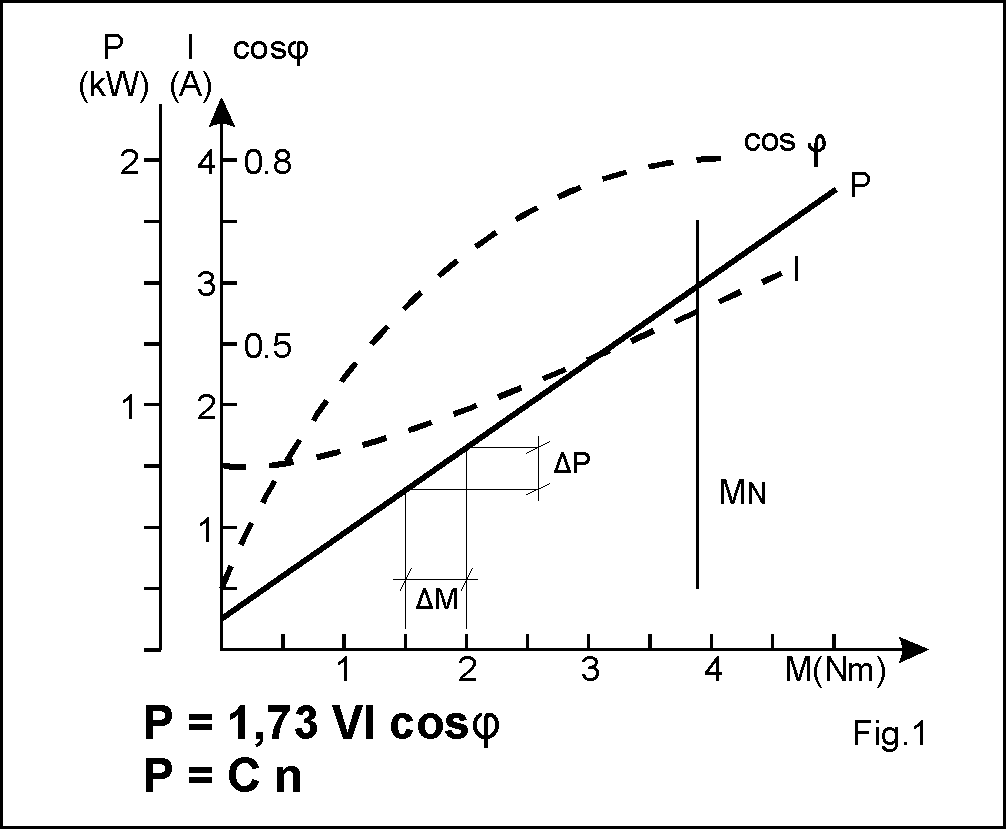
As showed by the diagram of fig. 1, the CURRENT (I), the POWER (P) and the COSφ do not behave in the same way in presence of the same load increase (resistant torque M indicated on the abscissa) .
The electronic relays EMIREL detect one or more electrical quantities of an asynchronous motor and compare it with a set value (set point), in order to get an alarm signal (sound, light, machine stop etc.). Consequently the devices are classified according to the parameter used.
There is a “FAMILY” of devices that has as reference quantity the CURRENT of the motor, they are the CURRENT RELAYS.
There is a “FAMILY” of devices that has as reference quantity the ACTIVE POWER that the motor absorbs by the mains, these are the POWER RELAYS.
Every family has its peculiarities, the current relays are less expensive but they have a different sensibility depending on unloaded or very loaded motor.
The power relays are more expensive but they have the same sensibility both with unloaded motor and with very loaded motor.
For a three-phase electric motor, connected to the three-phase mains, supplied by the voltage V, it is possible to write the following equation:
PE = 1,73 V x I x cosφ (WATT)
Considering : V = three-phase voltage of the mains
I = current absorbed by each phase of the motor
Cosφ = power factor (“Fi” is the phase displacement angle between the voltage and the current)
PE = power that the motor absorbs by the mains
The power PE absorbed by the mains allows the motor shaft to turn, so there is the conversion of PE into mechanical power, that is: PE=Pm=Cx n
Considering : Pm = mechanical power
C = master torque
n = number of motor shaft revolutions
(In the equivalence PE = Pm the motor internal losses are ignored).
The speed “n” depends on the number of motor poles and it is practically almost constant.
We write the PE=Pm with the quantities actually used: 1,73 V I cosφ = C x n (Equation A).
We suppose to have a motor of power P=5kW that with V=400Vac will have In=9A and cosφ=0,80.
The fully loaded motor will absorb by the mains at 400V 5kW absorbing the current I=9A for each phase with power factor cosfi and will give to the shaft a speed n=500/750/1000/1500/3000 RPM (depending on the number of motor poles).
As mentioned, the speed n remains quite constant, so there is a max torque Cmax such that Cmax x n = 5kW. (A) indicates that it is not possible apply a torque > Cm to the shaft because it would force the motor to absorb a power >5kW. In (A) n is constant so, if C must not exceed Cmax, the value of I or the value of cosφ or the total value P=1,73V I cosφ can be controlled. From these considerations the families of CURRENT RELAYS, PHASE RELAYS and POWER RELAYS originate. Always in (A), if C>Cmax, the motor is not be able to provide the speed n, so also the speed control generates a family of controllers: the SPEED RELAYS.
See the “FAMILIES” section for the choice of the most suitable limiter.
REMARK: The torque to be measured, to limit it, is a characteristic of the motor shaft, to measure it with mechanical torque limiters, the shaft should be cut and an element that measures the torque and that separates the load from the motor should be inserted, in case of intervention.
Often the speed of the motor shaft must be reduced to bring it to the appropriate value for the application, if a mechanical reducer which reduces the entering speed n1 to the output speed n2 is applied, n1C1=n2C2 therefore if n1/n2=30, C2=30C1, so the output torque is 30 times the input torque, so the output shaft will have greater dimensions and the application of a torque meter will be more expensive.
The electronic torque limiter, amperometric or wattmetric, is not applied to the slow shaft but it is applied inside the electrical panel where there is the motor contactor, for the Current Relays it is enough to detect the current of one phase (direct insertion or through CT), for the Power Relays also the three-phase voltage is required (obviously present in the electrical panel).
The electric motor, when supplied, provides a torque greater than the torque offered, so the possible mechanical torque limiter must be set above this value otherwise it would intervene at each motor start; instead the electronic limiter is equipped with a “TC” Timer which, when the current occurs, inhibits the intervention of the relay and therefore the calibration of the device is not affected by the presence of the torque peak.
From the Fig. 1 it is possible to obtain the characteristics of current relays and power relays: with the increase of M (resistant torque applied to the motor) it is possible to see that the absorbed power is a straight line therefore when the load increases of ΔM the power increases of ΔP and this happens in the whole field of M (unloaded motor or loaded motor).
The current does not have this characteristic, first of all it has a reduced dynamics (for example a motor with a rated current of 10A, with load at zero, has a current of 3-4A so the dynamics of the current is not 10A but 10A – 3/4A that is 7 or 6 A).
The trend of the current is not linear, it grows a lot when the motor is unloaded and less when the motor is loaded.