OVERVOLTAGES PROTECTORS
The most frequent questions are:
1. why should they be installed ?
2. where should they be installed ?
3. how should they be installed ?
4. how many of them should be installed ?
The answers to the above questions will come along with the following report.
INTRODUCTION
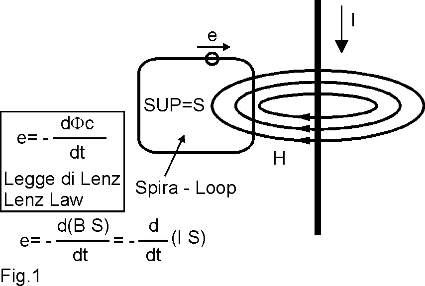
The Fig. 1 schematizes the phenomenon of an electric current I which runs through a wire nearby a loop S.
The impulsive current running in the wire generates an impulsive magnetic field H, which links up with the loop S. According to the LIENZ law, the loop becomes the origin of an electromotive voltage “e”, which may be very strong (such voltage is proportional to the loop extension (S) and to the current variation over time). If the loop is closed, the “e” generates a current, if the loop is open, it remains in the form of potential difference, that is a voltage peak.
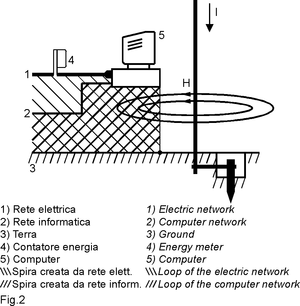
The Fig. 2 schematizes what happens nearby the “connection of a lightning rod to the ground”, run by the current I, and there are marked the loops that the ELECTRIC NETWORK and the COMPUTER NETWORK make up with the GROUND and the GROUNDING. So in these loops, which will be opened, an impulsive, high voltage for the connection with H will be originated.
The similarity between the two figures should show how the physical phenomenon is applied in the reality.
If in Fig. 2 the COMPUTER is replaced by a FAX and the COMPUTER NETWORK is replaced by the PHONE NETWORK it appears immediately, that also the FAX is involved with the same problems of the COMPUTER: furthermore, if the COMPUTER is replaced by a TV set, and the COMPUTER NETWORK is replaced by the connection to TV antenna, it will appear that also the house TV set will be affected by the same inconveniences.
The “connection of the lightning rod to the ground” can be replaced by the lightning itself which discharges from a cloud to the ground.
The lightning path is like a wire that guides the electrons of the electric discharge, around the discharge path, the magnetic field H will be intense and will couple with all loops that the external wires will form.
We become to answer to the 1st question:
Why should they be installed ?
Reply:
Because in some conditions the electronic sets around us can be damaged.
Let us see what it happens to the two wires of the CABLE which makes part of the LOOP.
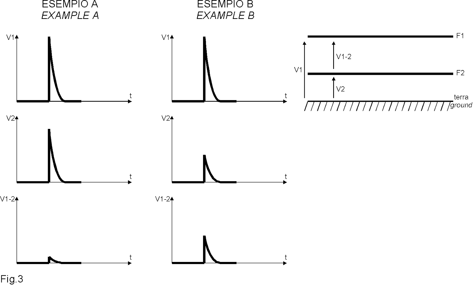
If the two wires make part of 2 “SIMILAR” LOOPS, they will be affected by 2 almost equal voltage peaks towards ground (Ex.: A – Fig. 3) and the potential difference between the two wires will be almost null: therefore it is requested to limit the potential difference of each wire towards ground with protectors installed between EACH WIRE and GROUND. If the two wires make part of 2 “DIFFERENT” loops, they will be affected by two peaks of different voltages (Ex.: B – Fig. 3), and a potential difference will be generated also between the 2 wires.
This report answers to the 2nd question:
Where should they be installed?
Reply:
They must be installed between wire and ground and between wire and wire. See the diagrams for the different models in the following page.
Obviously the protections cannot prevent the overvoltage peaks, but they must dissipate the peaks coming in, and they must not intervene in presence of the operation voltage of the cables.
As already noted, nowadays the technology provides a great number of electronic sets, which have the problem to be sensitive to the voltage discharges which may damage them also in an irreparable way.
Also the automatic machines present in the factories are equipped with electronic sets, and therefore the problem of protection against the overvoltages concerns both the industrial and the domestic field.
Let us go through an industrial or a domestic building in view of pointing out which are the problems involved, as far as the overvoltages are concerned.
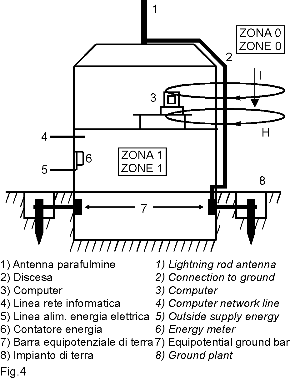
The Fig. 4 schematizes a building equipped with a lightning rod antenna, which will be hardly directly struck by lightnings, because the presence of the antenna protects the underlying area; nevertheless the PC nearby the antenna connection is not out of danger.
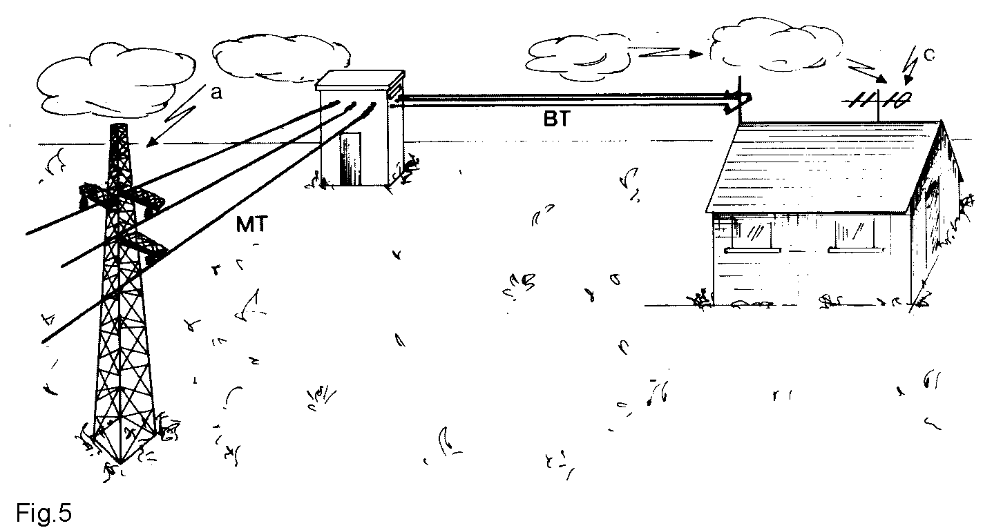
The schematization shows that the PC can be run over by a strong electromagnetic field, generated by the current of the lightning striking the antenna and discharging to ground. If the lightning does not strike this antenna, it may fall on the electric line nearby, and in this case the overvoltage may reach the PC through the electricity distribution mains (Fig. 5).
This example is useful to prove that the protection of a building equipped with an efficient grounding plant does not automatically prevent the overvoltages dangers which may occur to the devices present inside the building.
The presence of the lightening rod antenna, of the GROUND plant and of the equipotential bar help in any case to reduce the danger of direct lightnings strikes inside the building.
Two different ZONES are identified:
ZONE “1” THE INDOOR ZONE
ZONE “0” THE OUTDOOR ZONE
The protectors EMIREL are suitable for the ZONE “1”. The ZONE “1” is delimited also by the presence of the ELECTRIC ENERGY METER; as a matter of fact no protector can be installed upstream the meter, while downstream the meter it is possible to install the devices able to “dissipate” the energy generated by the overvoltages peaks entering the ZONE “1”.
It is necessary to point out that the electric energy supply line is the channel through which the overvoltage peaks collected by the electric lines in the ZONE “0”, (under form of direct or indirect discharges) can enter into the ZONE “1” (Fig. 5).
The electric energy supply line picks up also the voltage peaks caused by wrong operations along the line, by power factor correction plants which do not work correctly etc.
In the buildings there are: supply cables, COMPUTER NETWORK cables, ANTITHEFT SYSTEMS cables, etc., therefore many are the possibilities that some LOOPS are formed, that is some wires paths which occupy a certain surface. When this surface is run over by a magnetic field (for instance generated by the lightning current discharging to ground) the LOOP becomes the origin of an electromotive voltage and will tend to make run the current in the LOOP; if the LOOP is not closed, the spark may strike.
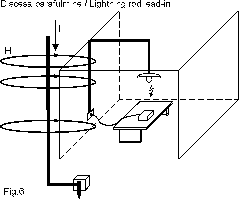
The Fig. 6 schematizes a case which happened in the reality: the I discharge current has generated a magnetic field H which is coupled with the open loop represented by the TOASTER on the table, with the electrical system and with the light bulb, generating a discharge between lamp and toaster.
We answer to the 3rd question:
How should they be installed ?
They are installed in relation to the set to be protected, and in function of the point from where the overvoltage is expected.
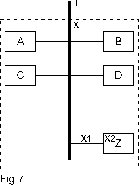
Let us make an example: Fig. 7 shows the layout of a factory where the supply enters through the point I and the machine Z is sensitive to the line overvoltages.
The first consideration to be made is that the overvoltages come most of the times from the outdoor line; it is therefore convenient to apply a protection system in the point X.
The machine Z shall have to be placed as far as possible from the point X, and another protection system shall have to be installed immediately before (X1), or immediately after (X2) the supply input.
In case overvoltages take place, the two protection groups will work almost in parallel, with the group X, which is more solicited than those placed on the machine Z. Also the machines A and B will take advantage of the protection made by these two groups. For the same reason, if also the machines A, B and C etc. are equipped in correspondence of their inputs with other protection groups, this would create a more articulated system of protection, since different groups of protection would work almost in parallel, and consequently the overvoltage energy would be more equally split up.
Let us reply to the 4th question:
How many of them should be installed ?
As already explained, we cannot prevent that an OVERVOLTAGE takes place, and we cannot even foresee its value.
Since the protection devices have the function of dissipate the overvoltage energy, it is evident that there is either the possibility to dissipate such energy with a few devices of high dissipative capacity, or with many devices of lower dissipative capacity. The right solution will result as a half-measure between the entirely technical aspect and the economic aspect. A practical rule suggests to apply “a great number” of devices of small capacity and place them according to a topographical criterion of cause and effect. (see Fig. 7 as example).
Fairly, we point out that it would be utopian to think of to be wholly protected after installing just one overvoltages protector. Besides, the voltage peak striking a line gives origin to the phenomena of transmission over the line and of reflection over the points of discontinuity of the line itself. For instance: a line ending in an empty current tap, causes a reflected peak equal to the incident peak, while if the tap supplies a set in operation, the reflected peak will be lower, but on the other side the operator will be struck by the incident peak.
The phenomenon of the peaks reflection in practice make the whole electric network affected by the overvoltage which has struck it in just one point.
For this reason, it is a good rule to distribute the protections all over the electric network in a uniform manner, likewise the “salt on the dishes”.