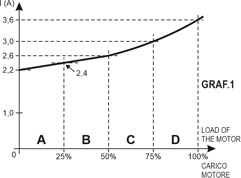
If we consider a motor 1,5 kW, 400V, IN=3,6A and with a brake on the shaft, we load the motor up to 100%, detecting the value of the current I, we obtain the GRAF. 1. We see that the values of the current I are not linear with the load: up to 50% the increase of the current is little (UNLOADED MOTOR), from 50% to 100% the increase of the current is bigger (LOADED MOTOR). Besides the dynamics of the current, for the load from 0 to 100%, is not 3,6A but
3,6A-2,2A=1,4A.
(I=2,2A is the motor “loadless” current, absorbed by the motor with load = 0 on the shaft).
We can divide the applied load in 4 zones:
0–25%, 25÷50%, 50%-75%, 75%-100% and we can get the change of the current for 1% of the change of the load (it will be: mA / 1% LOAD)
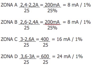
Therefore if we suppose an increase of the load of 10%, if the motor is run in the zone B, we get an increase of the absorbed current of 80mA, while the same increase, if the motor is run in the zone D, will generate an increase of the absorbed current of 240mA.
It is evident that an AMPEROMETRIC relay, (which measures the current absorbed by the motor and compares it with a SET POINT), is efficient only in the zone of LOADED MOTOR.
The calibration of the set point in A or B zone (where I increases a little), implies that the SET POINT will have to be chosen very close to the value I in the motor at the time of calibration, so will be possible that the relay will trigger too often or too seldom.
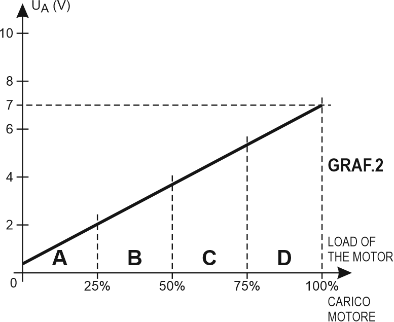
If we use A1L1 on the same motor, the current measured from A1L1 is that of GRAF. 1, but it is “linearized” and used for the internal SET POINT, and it is also on the analog output (GRAF. 2).
We can see that it is a straight line, on the base of the load applied to the motor, and there is not difference between “unloaded” and “loaded” motor.
With I=3,6A we select the range 5A; at 5A correspond 10V in the analog output, so at 3,6A will correspond 7,2V in the analog output.
Therefore the dynamics of the signal is
7.200mV = 7.200mV = 72mV/1%
100%
This value is much greater than the values of the 4 zones and it is constant for all zones A,B,C,D.
For the customer who complains: “the amperometric relay XX sometimes triggers…. sometimes not”, we can suggest the use of A1L1.